
Custom L Brackets
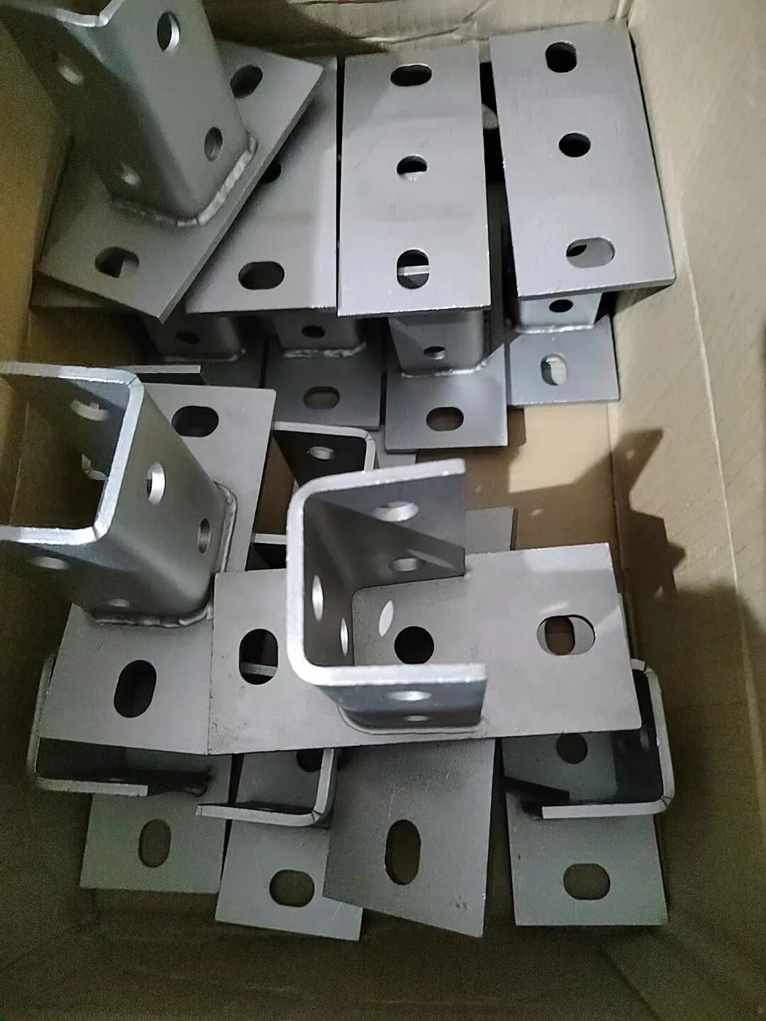
Custom stamped and bent L brackets made to your drawing for machinery, electrical enclosures, panels and OEM assemblies. One 90° bend, two legs, and a set of holes that have to line up with whatever the bracket mounts to — simple in principle, and decided almost entirely by details that are easy to leave off a drawing.
We review the bracket geometry, material, thickness, hole pattern, bend sequence, surface finish and order quantity before production. Where a dimension is critical to the fit, it is worth marking on the drawing: an L bracket is usually rejected for hole position relative to the bend, not for the bend angle itself.
Where L brackets are used
- Mounting brackets for sensors, switches and small enclosures
- Shelf and panel supports in cabinets and control boxes
- Frame corner joints and gusset plates in fabricated assemblies
- Motor, pump and gearbox mounting feet, where flatness of the base leg matters
- Brackets welded or riveted into larger assemblies
What decides whether an L bracket fits
Three things, in this order of frequency:
- Hole position after the bend. Holes are punched in the flat and move when the part is formed. If a hole is dimensioned from the outside of the bend, the bend allowance has to be right before the part can fit. Dimensioning from a hole in the other leg to a hole in this one removes that dependency.
- Leg length and squareness. A bracket that is 0.5 mm long on one leg can still fit. A bracket that is not square puts the mounted component out of alignment, and that is what the operator notices.
- Inside radius against the mating part. A sharp inside corner is not free: the punch needs a radius it can survive, and a component sitting into the corner needs the radius the drawing actually allows.
Bend radius, springback and the second operation
Every bent part relaxes slightly when the punch withdraws. Springback is predictable for a given material, thickness and radius, so it is compensated in the die rather than corrected by hand — but it does mean the bend angle should be toleranced rather than assumed exact. Where the angle is critical, the practical options are a tighter die and inspection of the angle, or a design that tolerates ±1°.
If the bracket needs holes in both legs, decide whether they are pierced before forming or drilled after. Piercing before forming is faster and cheaper; drilling after forming guarantees position relative to the finished part. On a bracket where the two legs must align with a mating component, that trade-off is worth settling before tooling.
Materials and finishes
Carbon steel, stainless steel, aluminium and copper can be reviewed according to your drawing and application. Q235 covers most indoor brackets; SPCC gives a better surface and tighter thickness tolerance; 304 stainless is the choice where the bracket sees moisture or cleaning chemicals. Thickness runs from 0.5 mm to 10 mm.
Surface treatment options include zinc plating, powder coating, electrophoresis, deburring or another project-defined finish. Zinc plating is the usual answer for a bracket that is handled and hidden; powder coating where the bracket is visible or colour-matched to a housing. Plating adds lead time and can change final dimensions on tight features, so finish and tolerance should be reviewed together rather than in sequence.
Tolerances worth marking on the drawing
- Hole-to-hole spacing, where the bracket mates with two fixed points
- Hole position relative to the bend line, if the mounted part must sit at a fixed height
- Squareness of the two legs, where alignment is visible or functional
- Flatness of the base leg, where the bracket sits on a stamped surface
- Burr direction or maximum burr height, if the bracket is handled in assembly
Everything unmarked is treated as general tolerance. Tightening a tolerance that no interface needs raises the tooling cost and the inspection burden without improving the assembly.
From drawing to repeat production
- Drawing and feasibility review, with any open points listed
- Material, tooling and process planning — single-stage die or press-brake, depending on volume
- Sample production within 7 days of confirmed requirements, with a dimensional report
- Approved revision and repeat-order production in 15–25 days after approval
Specification summary
- Materials: Q235, SPCC, 304 stainless, copper, aluminium
- Thickness: 0.5 mm to 10 mm, confirmed per drawing
- Presses: 30T to 400T
- Finishes: zinc plating, powder coating, electrophoresis, deburring
- Samples: within 7 days of confirmed requirements
- Production: 15–25 days after sample approval
Questions we ask before quoting an L bracket
Is the bracket right-angled, or does it need an acute or obtuse angle?
Anything other than 90° is still ordinary bending work, but the die is dedicated to that angle. If the angle may change later, say so — it affects whether the tooling is worth amortising over the first order.
Do the holes need to align with an existing part?
If they do, send the mating part or its interface dimensions. Hole position relative to the bend is the most common reason a first sample does not fit, and it is avoidable at quotation.
Is the visible face the inside or the outside of the bend?
It decides where the burr goes and which face the finish has to be good on. Both are cheap to specify and expensive to change after plating.
Request a quote
Please send your drawing, material, thickness, surface finish, required quantity, critical tolerances and target delivery date. If any of those is still open, send what you have — we will list the assumptions in the quotation so they can be confirmed before tooling.
All product families · U brackets · Mounting plates · Stamping FAQ
KEEP READING